
ITB PERFORMANCE LINKAGE TIPS INTRODUCTION TO ITB SYSTEMS
Some of the biggest problems people have with ITB intakes and in particular side draft carburetors is actually cause by incorrect linkage configuration.
Independent runner intakes require some special attention when it comes to having a perfectly balanced system. Firstly lets examine the operation at idle or low opening operation.
At idle there is only a very small amount of air needed for each cylinder and the amount of fuel must match the air in a perfect ratio for correct combustion. The opening in a butterfly at idle is VERY small typically only about 010″ (0.25mm) if the opening is +/- .001″ then that runner will deliver more or less air than the others.

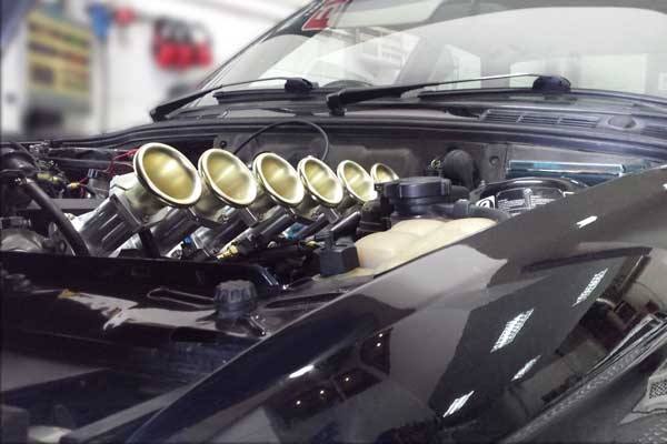
BMW 6 CYLINDER ITB KIT FITTED
Not only will that cylinder be out of balance and trying to run faster or slower than other cylinders it will also be badly out of tune because the injectors will still be delivering the same fuel to all cylinders, the result is an engine that will miss and run rough.
Think about that for a moment that’s only a tolerance of 0.002″ (0.05mm) to be out of balance!!! How often have you been at a race track and heard a car come in with Weber carburetors and its going Flut, flut, flut, sputter, sputter, flut, flut.
Nine times out of ten that is caused by the incorrect linkage setup, and people will complain about webers always going out of tune or going out of balance but Ferrari didn’t use webers on there engines for them to need tuning every month!!!
There is no reason why a side draft carburetor or ITB set up can’t be used on a daily driven vehicle for years and years, always idling perfectly and never needing adjustment
“Ferrari didn’t use multiple Weber’s on there engines for them to go out of tune every month!!! “
There are two basic configurations and many misconceptions when it comes to each style of linkage and its appropriate application.
The first style and most WRONGLY used consists of a secondary shaft usually just above the butterflies and several individual drop links to each carburetor or throttle body.
Similar configurations are often seen on OEM ITB applications and so people tend to think this is the best option for their aftermarket ITB or side draft carburetor set up, but the fact is this could not be further from the truth!
OEM manufactured systems have some very important differences. Firstly they all have a factory cast manifold that is made with many rigid precision supports for the secondary shaft! usually supported in multiple needle bearings above each runner. They also have high precision style ball ends on the link to minimize any slack or movement and lastly they have a large common passage cast into the manifold that connects all the runners together so this will equalize the pressure between the runners and allow each cylinder to receive the exact same amount of air, even if the throttle plates are not perfectly synchronized they also use this common passage for introducing air from the cold start and idle control valve etc.
For this reason the butterflies of each throttle do not need to be perfectly synchronized at all times, but it also means the system will get a lot of cross communication between the cylinders which will upset the idle quality a lot when running cams with large amounts of overlap.

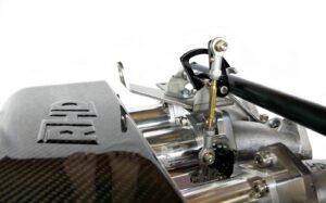
Note the large balance tube and large 10mm linkage shaft supported in needle bearings next to each drop link on this oem ITB from an M88 BMW engine
Click to enlarge. When this style is applied to carburetors or aftermarket ITB’s there is no way that any of the linkage components can remain rigid enough to keep all the butterflies within that .002″ tolerance.
Remember all the oem systems have a common passage connecting the runners so that at idle all the butterflies can be closed or slightly unbalanced and they will still equalize.
But without this for one runner to be balanced to the next one there is always a series of links and shafts to transmit the movement from one body to the next and this series of links will all have flex and movement in the bearings and bushings which all accumulates adds up to much more than the 002″ required to keep them perfectly balanced.
Even changes in temperature or the pulling action of the cable on the secondary shaft will cause more flex than this.

Here is an example of probably the WORST possible set up, notice the small flimsy shaft along the top with the second link attaching right in the middle where there is no support and the cable attachment also right near this point adding all sorts if additional flex and movement to the drop link. A setup like this will be an ongoing nightmare!
Each throttle will need to have its own throttle stop and the links will need to lift them off the stops perfectly simultaneously. The reality is that this will never happen! and even if this is perfectly and painstakingly adjusted to work initially, after a bit of driving and temperature cycles, the linkage components wear a little and in no time at all they are out of balance again. This might be ok for a race car where the only slow driving required is off the trailer and out of the pits, after that its mostly high opening operation.
I even like my race cars to idle well and drive smooth at light throttle. For a road car we all definitely need something that will stay reliably balanced for years.
THE ONLY CORRECT WAY IS TO HAVE ALL THE SHAFTS COUPLED TOGETHER AXIALLY!.. With ONE Throttle acting as the master with idle stop and single actuation lever.
But hang on!!!!….. Then why have I seen similar configurations on OEM side draft carburetors too!
Well quite simply because the makers of the carburetors were not involved with the fitment of their product onto the vehicle, and here I’m talking specifically about Australian Chrysler and Holden when they released limited numbers of cars for racing, such as the e49 Charger and Holden XU1.
They half got it right but at the time in Europe most vehicles used 4 cylinder engines so the carburetors all came in pairs with the correct balance coupling.
If the engines had 6 or 12 cylinder like Porsche or Ferrari then two 3 barrel carburetors would be used for each bank of 3 cylinders again with one correct balance coupling but due to the high cost and limited sizes of these 3 barrel units when the Australian manufacturers came to purchase something for their 6cyl engines they opted for 1.5 sets of a 4 cyl system.
So what they had was two units nicely linked together as they should be and one additional all on its own. But instead of fitting a second balance coupling like they should have they opted for the notoriously bad design of using 2 drop links!
Its only here in Australia that you will find this set up, all the European manufacturers used the correct method. In the heyday there were a handful of weber specialists who grew to hero status for their legendary ability to fix and tune side draft draft carburetors, people would rave about how they had continual problems for years until they took it to said tuner and after that the car was such a pleasure to drive and never gave any more problems!….. All they would do is toss out the double drop link system and fit a second coupling so all the shafts were joined axially, while nicely removing large amounts of cash from the owners pocket for the pleasure of doing so!

Here is a picture of the notoriously bad Aussie special, where one pair is linked to the lonely third by a secondary shaft. Just the simple act of the cable pulling on the linkage installs all sorts of play and flex to the linkage, this could easily be as much as 0.5mm!
Now this might not sound like much but remember its about 10 times the acceptable amount for smooth synchronized running, badly upsetting the idle and low speed running quality just off idle. Then add to this any tiny amount of wear or play in the system and you can plainly see that right off the showroom floor this setup was an epic failure!!
THE SOLUTION!
Enter the second style of linkage. This is how ALL side draft carburetor and aftermarket ITB linkages should be configured.
A secondary shaft is still ideally used apposed to having the cable or linkage acting directly on the ITB but this only needs to be short and the rigidity is not critical.
From this shaft ONE drop link is used to connect to ONE carburetor or ITB. The drop link attaches to one single linkage arm on the ITB or carbie which will also have an idle adjustment screw and wide open stop. It does not matter what particular body this master link is attached, but this then becomes the primary control for all the others.
Then from this master ALL the others are connected directly off the shafts with an adjustable spring coupling. Only use ONE idle adjustment screw.
Once they are set up like this and balanced the first time no amount of wear or flex on any of the linkage parts anywhere will affect the synchronization.
All RHD throttle body sets and kits come with spring loaded balance couplings with grub screw and lock nut design that allows very fine adjustment for synchronizing the butterflies. Much the same as factory Weber and Dellorto carburetors are supplied with as standard equipment.
Here can be seen the correct way to link the bodies on this diagram from Weber carburetors. The balance coupling parts can be seen here labeled D E & F
RACEHEAD LEADING THE PERFORMANCE CHALLENGE.

STATEMENT RELEASED DIRECTLY BY THE MAKERS OF WEBER CARBURETORS
A Weber Carburetor system will not be right, unless it’s synchronized to ensure that each carburetor is doing exactly the same as the next – the name of the game is perfect cylinder tuning. The synchronization procedure can either be a breeze or a nightmare, depending on whether you have a well-designed linkage system or not. The secret to a good linkage set-up is that it must allow independent adjustment of each carburetor without affecting all the rest as you go through the procedure. Here again, if someone tells you they’re absolutely impossible to synchronize, you might study his linkage. Chances are, it’s incorrect and he’s fighting himself.
HOW TO SYNCHRONIZE ITB’S USING A SYNCHROMETER
So all this leads us to the last installment of this article and that is how to properly synchronize your intake. First up you will need to buy or borrow one of these
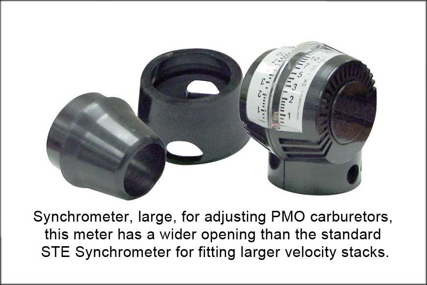
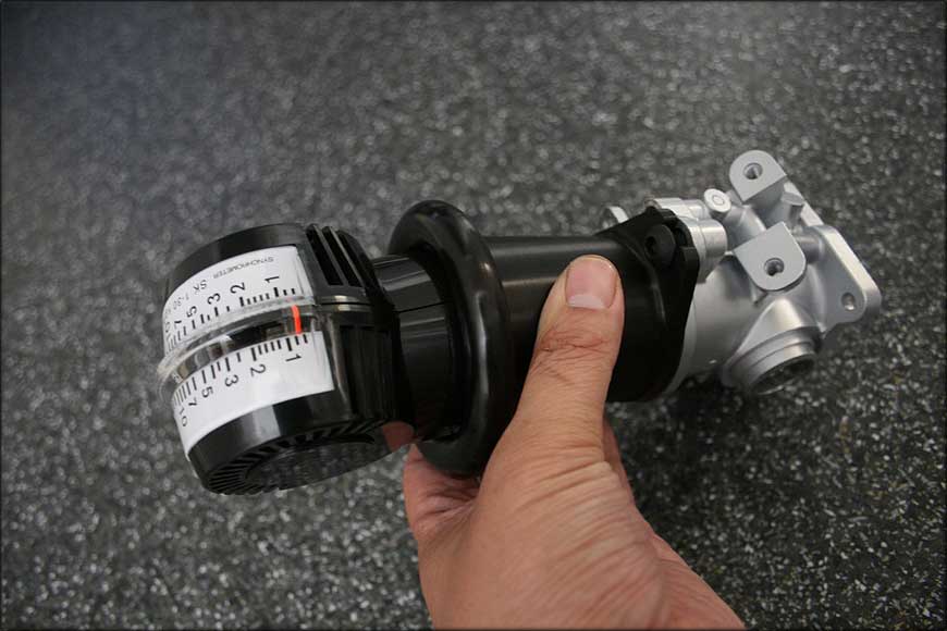
There are several different designs but they all do the same thing, they accurately measure the flow of air into the velocity stack. Firstly try to have all the butterflies close at exactly the same time as best you can, open the idle screw all the way out so that the butterflies are all tightly closed then make sure each body also has the butterflies closed and the coupling is preset with adequate adjustment in both directions when you lock the couplings to the shaft.
Then set the idle open a little and start the engine. Set the idle slightly high 1200-1500 rpm is fine just so that the engine runs smoothly enough not to hunt up and down. Then measure the flow into the body with the master linkage attached first.
Then measure the next one and adjust the coupling so the flow matches the first, the engine should get smoother and the flow into the first may change so go back and forth.
Then move to the next one and adjust the coupling in the same way until the flow also matches the master and once again the engine should get smoother.
Now set your idle back closer to the required idle speed and go back and check the flow of each cylinder and re adjust if needed.
Remember the better the synchronization the better and smoother your engine will run.